Microtubule Motility Assays
As the pivotal role of microtubule (MT) motors in the cell cycle becomes more widely recognized, so the demand for motility assays will increase. This article presents a robust and straightforward set of protocols based on experience gained in our laboratory. Readers seeking to set up more specialised assays should refer to one of the excellent methodological compendia that are available (Inoue and Spring, 1997; Cross and Kendrick Jones, 1991; Scholey, 1993).II. MATERIALS AND INSTRUMENTATION
A. Hardware
1. Microscope
Unstained MTs are visualized most conveniently by video microscopy using computer-enhanced differential interference contrast (DIC). MTs assembled from fluorescently labeled tubulin can be visualized using epifluorescence. This article concentrates on these two contrast modes. It is also possible to visualise microtubules by dark field, which gives a high contrast image of unstained microtubules, or by phase contrast, but both modes are susceptible to dirt in the solutions and so may be inconvenient for routine work. Interference reflection produces higher contrast than DIC and gives information in the Z direction, but again is susceptible to dirt.
For all modes of contrast the main requirement of the microscope is that it should be as simple as possible. It should also be big and heavy to give it some vibration resistance. Uprights are less expensive, optically straightforward, and more convenient if the bathing solution is to be exchanged during observation (which is often the case). Inverted scopes are more stable and provide much better access to the specimen if other inputs (micromanipulators, flash-photolytic lasers, evanescence prisms) are envisioned.
Human eyes work in colour and have a higher dynamic range, better spatial resolution, and a bigger view field than a video camera. It is very useful to be able to use them to find focus. To do this the microscope needs to incorporate some sort of device to switch the light between the eyepieces and the camera.
2. Illumination
One hundred Watt Hg lamps generate large amounts of heat and it is necessary to remove this heat from the illuminating light. Glass heat filters may be used, but the best way to filter out heat is to use a hot mirror, a mirror that transmits infrared but reflects visible light (technical video).
DIC optics are optimised for visible wavelengths, and it is conventional to use a green interference filter to give narrow band illumination. In practice the improvement this brings is often too slight to be obvious by eye, and removing the green filter can be a convenient way to brighter illumination. The UV emitted by Hg lamps is removed substantially removed by optical (lead) glass, but for DIC an in-line UV filter is nonetheless a sensible precaution.
A useful improvement in both fluorescence and DIC image quality can be achieved by sending the illuminating light through a fibre-optic light scrambler (Technical Video). Light from the lamp is focussed into one end of the fibre (Fig. 1), and the other end emits a uniform disc of light (of Gaussian intensity profile), which is used to illuminate the microscope.
3. Optical Train
For maximum image quality in all contrast modes, it is advisable to reduce the number of optical components between the objective and the camera to a minimum. The most critical component is the objective. The light intensity transmitted by a lens is proportional to the square of its numerical aperture (NA), whilst resolution rises linearly with the NA. It is important therefore to use a 1.4 NA (therefore oil immersion) 60 or 100× planapo objective in order to maximise light-gathering power and resolution, particularly so in epifluorescence, where the objective doubles as the condensor.
We use a novel configuration that replaces the condensor on a Zeiss Axiovert with a home-built fitting that improves light collection from the Zeiss tungsten lamp and mounts a second objective in place of the condensor. This arrangement (Fig. 1) gives good MT DIC with a field about 40µm and brings the considerable advantages of the tungsten lamp, which is much more stable than the Hg lamp. For smaller view fields, the higher radiant intensity of the Hg lamp is necessary.
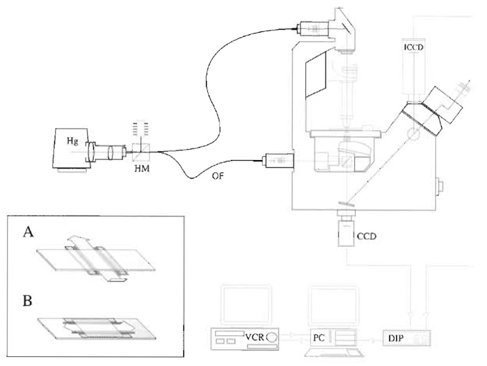 |
| FIGURE 1 Video microscope. An inverted microscope set up for both fluorescence and DIC microscopy. Hg, mercury lamp; HM, hot mirror; OF, optical fibre; CCD charge-coupled device camera (for DIC); ICCD, intensified CCD (for fluorescence); DIP, digital image processor; PC, personal computer; VCR, video cassette recorder. |
4. Antivibration Hardware
Vibration will degrade the highly magnified image. Low frequencies (people walking across the floor) will cause the image to bounce around, whilst high frequencies will be averaged out by the video framing rate and cause the image to blur. The extent of this problem is, however, often overemphasized. Before purchasing an expensive and awkward vibrationdamping equipment, try placing a few layers of bubble wrap under the microscope baseplate.
5. Temperature Control Hardware
Motility rates for several motors are extremely temperature sensitive in the range of room temperature, and temperature control is consequently important if measurements taken at different times are to be compared. The best way is to temperature clamp the entire microscope. If you have air conditioning this will already be happening. To warm specimens above ambient temperature, we use a homemade plexiglass box with a warm-air blower coupled to the side. Another option is to use water jackets for the objective and stage. These are readily fashioned by wrapping flexible, narrow-bore copper tubing around several times and connecting the ends to a water bath with a circulator (e.g., Techne) using silicon tubing. If cooling is necessary, we find it useful to wrap the microscope in a tent made of cling film, reducing condensation.
6. Camera
For fluorescence of moving objects, two types of low-light level / high-contrast / high-framing rate cameras are suitable: intensified charge-coupled device (ICCD) and intensified silicon-intensified tube (ISIT) cameras. ICCD cameras are better for current purposes because ISIT cameras, although more sensitive, introduce spatial and intensity distortions across the view field that are tedious to correct for. All the aforementioned produce an analogue video signal, e.g., ISIT Hamamatsu C2400-08 and ICCD Hamamatsu C2400-97E. An alternative approach that is becoming feasible uses a digital camera to record direct to computer hard disc in time lapse. A cooled CCD camera coupled to a generation 4 intensifier gives excellent sensitivity for fluorescence work, but is limited by the quantum efficiency of the intensifier (about 30%) and is currently very expensive and the digital data can be awkward to archive. If considering this route, be sure to test the software, which in our experience can place more severe limits on performance than the specifications of the hardware.
For DIC, a nonintensified scientific grade CCD is fine, e.g., grey-scale CCD camera Hamamatsu C2400 77e.
7. Camera Coupling/Magnification
The ideal magnification sets four or more camera pixels across the width of the MT. For a 512 × 512 pixels (2/3in.) CCD, this corresponds to a square field with sides of 20-25µm. Zoom couplings are wonderfully convenient but are not always a good idea because they absorb a lot of light. Magnification must be calibrated using a stage micrometer.
8. Image Processor
CCD cameras are often offered with a hardware box providing real time analogue enhancement of the video signal (any or all of gain, back-off and shading correction). A digital video processor is better, which is able to digitise incoming video frames, perform frame averaging, contrast enhancement, background subtraction, and caption overlay and then re-encode the image as an analogue video signal, all in real time. The Hamamatsu Argus 20 is so well thought out that it is virtually standard equipment for video microscopy laboratories. The best and most flexible arrangement is to adjust the gain and backoff on an Argus 20 or similar processor controls such that there are no areas in the image that are completely saturated and then apply further digital enhancement. The resulting signal is displayed on a monitor and is fed to the PC for direct grabbing of video clips and to the VCR for archiving.
9. Monitor
It is worth investing in a high-quality 14-in. multiformat monitor. Larger monitors look impressive but are only helpful if they have to be placed a long distance from the operator.
10. Video Recording
At the time of writing, the most convenient and practical way to store large amounts of video is still to use video tape. Recording to VCRs inevitably involves some degradation of the image (loss of spatial resolution, noise, contrast effects). For practical purposes the resolution loss is potentially the most serious problem. The effective resolution following recording can be visualised by recording and replaying a test card image having black and white lines at various spatial frequencies. Currently the best option is digital recording to video tape. Digital video tape recorders input and output an analogue signal, but encode data digitally to tape. The digitization involves some compression of the incoming video signal, but most of the compression is on the chrominance rather than the luminance, with the result that spatial information is relatively well preserved, particularly for grey-scale signals. Unlike other compression schemes such as DVD, there is no compression along the temporal axis. There are currently two sizes of tape: digital video (DV) and mini-DV. There are also two different formats: DVCAM (Sony) and DVCPRO (Panasonic). These two formats use the same compression scheme but DVCPRO spaces the tracks further apart on the tape, giving (arguably) better reliability and accuracy for editing, but with correspondingly less recording time on the tapes. Digital video recorders tend to be built for the pro market and are more robustly engineered than consumer machines, but are also more expensive.
We have evolved a video-recording strategy that offers maximum flexibility: Time-lapse digital recording of grabbed video frames to computer hard disc (with no resolution loss) and simultaneous realtime recording to digital VCR. The VCR runs uninterrupted in the background and generates an archive. The operator is free to go back to this archive at a later date and transfer interesting sequences to the computer for analysis. Captured digital sequences can be archived to external hard discs. We now have a fast digital capture and analysis application RETRAC II, which allows batch digitisation of video clips from tape for subsequent analysis. RETRAC II can be downloaded from our website (http://mc11.mcri.ac.uk/ Retrac / index.html).
Analogue video recording is still in widespread use. Different video formats unfortunately operate in different countries. In the United States and Japan, NTSC format applies (525 lines per frame; 30 frames/s, typically captured at 640 × 480 pixels). European countries use PAL, which has higher spatial resolution but lower time resolution (625 lines per frame, 25 frames per sec, typically captured at 768 × 576 pixels).
11. Computing
The most convenient way to analyse motility is to capture a sequence of frames into computer memory and to track objects using a mouse-driven cursor. It helps to have a hard disc big enough to hold 2 day's work (more is dangerous because of the temptation not to back up) and enough hard memory to hold the stack of captured frames. A typical 20 frame stack uses about 8 Mb of application memory; if you want to use larger stacks then you need more memory. Processed stacks can conveniently be archived to removable discs. We use 100-Mb zip discs or 230-Mb magneto-optical discs. CD writers are getting less expensive and are worth considering if a permanent archive is required. Video compression protocols (JPEG, MPEG) are best avoided, as all involve some data loss. That said, Quicktime has become a standard for digital video and can use a variety of compressors, some of which are lossless.
12. Frame Grabber Card
Large numbers of video grabbing cards are available. Only a few are supported by Retrac and NIH Image, the freeware software packages that are recommend later. Because the situation is fluid, please check the software documentation for a list of supported cards.
13. Software
On the Mac, the best route for analysis is NIH Image, which can be customised using macros to track objects and output data in spreadsheet-compatible format. Macros for basic tracking through NIH Image stacks are available for download from our web page http:// mc11.mcri.ac.uk/retrac.html. NIH Image runs on system 9 macs, with support for the Scion LG3 frame capture board, or in classic in OSX but without the Scion support. Wayne Rasband is continuing development of ImageJ, an NIH imageminspired java programme that runs in OSX and currently has partial support for the LG3 board (http://rsb.info.nih.gov/ij/). NIH Image and ImageJ are both available for the PC.
RETRAC 2 for Windows is purpose-written for the analysis of motility assay data. The latest version supports time-lapse frame grabbing from either VCR or live video, autofocus, autocontrast, tracking (including drift correction) spatial filtration, and magnification. The programme now incorporates a powerful file manager. Figure 2 shows a screenshot during tracking.
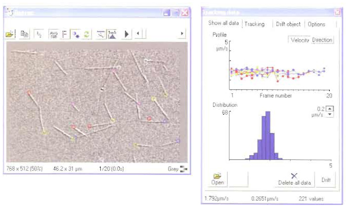 |
| FIGURE 2 A screenshot from RETRAC 2. |
14. Glassware
The type of slide used does not matter. The type of coverslip does. The thickness of the coverslip should be matched to the objective. The objective will be marked appropriately [e.g., 60/planapo DIC 1.4 0.17/160 means a 60× objective selected as strain free for DIC, aplanatic (flat field); apochromatic (low chromatic aberration for blue yellow and green); optimised for cover glasses 0.17mm thick and with a 160-mm focal length]. We use Chance 22 × 22-mm No.1.5 coverslips. In the past we have used these without any special cleaning treatment and rejected "bad" batches of coverslips that show poor binding of motor and/or a poor image because of surface contamination. This is still a workable approach, but we have begun to use a cleaning procedure that appears effective in removing contamination and making the coverslip reproducibly hydrophilic, as evidenced by the spreading of a drop of buffer placed on the surface so that it wets the entire surface. This coverslip cleaning procedure is based heavily on that given on the Technical Video website (http://www.technicalvideo.com/Products/ CCP.html). Our localized variant is on our website (http://mc11.mcri.ac.uk/protocols.html).
III. PROCEDURES
A. Taxol-Stabilised Microtubules
Solutions
- 1M K-PIPES: PIPES dissolves around its isoelectric point of about pH 6.5. Take 500ml water, add 65 g solid KOH, and then, after cooling if necessary, slowly add 302g PIPES buffer (Sigma P-6757). Once everything is dissolved, monitor pH and roughly adjust by adding more KOH pellets as necessary. Allow the warm solution to cool and then fine-adjust pH using 5M KOH. Be careful not to overshoot, as there is no way back.
- 100 mM NaGTP stock solution: Because nucleoside triphosphates such as GTP and ATP undergo rapid hydrolysis at acidic pH, efforts should be made to control pH when dissolving and storing them. Dissolve 1g NaGTP (Sigma G8877) in 15ml 10mM Na- PIPES, pH 6.9, monitoring pH. Rapidly reneutralise pH by titrating in 5M KOH. Fine adjust pH and then make volume up to 19.11ml. Store frozen at -20°C in aliquots of 5-2000µl. Do not add MgCl2 to the stock solution (it precipitates).
- 100 mM MgATP stock solution: Dissolve 5.87g NaATP (Sigma A7699 ATP ultra or Boehringer 519 987) in 60ml 10mM K-PIPES, pH 6.9, monitoring pH continuously and holding as close as possible to neutral using concentrated KOH. Once the ATP is dissolved, add 10ml of 1M MgCl2 and readjust pH to 6.9. Adjust volume to 100.0ml and freeze in aliquots of 5-5000µl.
- Taxol stock solution: Wear gloves and work in the fume hood. Inject 2.93ml anhydrous dimethyl sulfoxide (DMSO, Aldrich 27685-5) into a 25-mg bottle of taxol (Sigma T 7402). Dissolve by vortexing and store as 2- to 20-µl aliquots at -20°C. Taxol is stable in DMSO but unstable in water. It is insoluble in aqueous buffers above about 18 µM. DMSO is explosive if it gets wet. Store small volumes at room temperature over beds of Sephadex G-50.
- 0.2M NaEGTA: Dissolve 15.2g EGTA (Sigma E 4378) in 190ml water. Adjust pH to neutral by adding concentrated NaOH and then make volume to 200.0ml. Store at room temperature.
- 1M MgCl2: 20.33 g MgCl2·6H2O to 100 ml water. Sterile filter and store at room temperature.
- BRB 80 (Brinkley reassembly buffer): 80mM KPIPES, 1 mM MgCl2, 1 mM EGTA, pH 6.9. Make up as a 10× stock, store at 4°C and dilute freshly for use. Purified tubulin at about 100µM (protocol for tubulin preparation on our web page) in BRB80 should be flash frozen in 10- to 25-µl aliquots in the presence of 30% glycerol by immersion in liquid nitrogen and stored either at -70°C or preferably in liquid nitrogen.
Steps
- Thaw an aliquot of tubulin (typically 200µM) and add stock 100mM NaGTP to 1 mM and MgCl2 to 2mM. Warm to 37°C and incubate for 20min.
- After 20min, add taxol from a 10mM stock in DMSO to 20 µM final. Dilute microtubules 1000-fold for use using BRB80 buffer supplemented with 20 µM taxol.
B. Preparation of Flow Cells
Steps
- Apply single-sided Scotch tape to the long edges of a microscope slide such that the strip of glass surface between the two pieces of tape is 8-10 mm wide. Trim away overhangs with a razor blade.
- Extrude two parallel stripes of Apiezon M grease from a syringe with a squared-off wide-bore needle along the inner edges of the tape strips.
- Press a clean coverslip onto the grease. The volume of the flow cell can be adjusted by spacing the grease strips apart and/or by placing spacers between the coverslip and the slide. Single-sided Scotch magic tape is about 50µm thick, giving a flow cell of about 10mm × 5mm × 50µm, or 25µl. Thinner metal or cellophane foils can be used to make a shallower flow cell and conserve sample. It is helpful to make the flow cell shallow because the microtubules below the top surface scatter light and reduce contrast. For inverted scopes, it is convenient to arrange flow crosswise. The inset to Fig. 1 illustrates flow cells for inverted (A) and upright (B) microscopes.
C. Surface Adsorption of Motor
Solutions
- Motility buffer: BRB 80 plus 1 mM MgATP. For fluorescence work only, degas and add 1% of 100× antibleach mix (GOC), which is 100mg/ml glucose oxidase (Sigma G7016), 18mg/ml catalase (Sigma C100), and 300mg/ml glucose (Sigma G7528) in BRB80 plus 50% glycerol. When aliquoting, fill tubes to exclude oxygen, cap, and store at -20°C.
- 100× diluted MTs: either motility buffer or motility buffer plus GOC.
Steps
- Place the flow cell fiat. Using a Gilson, inject into the cell 1 chamber volume of motor solution. The solution is drawn into the cell by capillarity. Incubate the slide in a moisture chamber for 2-5min at 20°C to allow the motor to adsorb to the glass.
- Wash the cell with 2 chamber volumes of assay buffer, applying the solution to one side of the chamber using a micropipette and drawing the solution gently through the cell using the capillary action of the torn edge of a strip of Whatman 3 MM, placed at the exit of the chamber.
- Flow in 1 volume of MTs in motility buffer + taxol and mount the slide on the microscope stage, oiling the condensor to the bottom of the slide (it may be possible to use a dry condensor for quick-and-dirty assays).
- Extra for fluorescence work 1. Degas some BRB80. To 10ml, add 100µl of 100× GOC. Take another 3ml and add MgATP to 2mM. Fill and cap tubes to exclude oxygen and hold buffers on ice. Add taxol to 20 µM freshly before use.
D. Microscope Setup
1. DIC
Before the day's work, align the microscope roughly using a test specimen (a slide made using a suspension of plastic beads provides a stable and realistic test specimen). Switch on the lamp and allow a few minutes for the arc to stabilise. Rack down the objective and oil it to the slide. Insert some neutral density filtration to protect your eyes from the intensely bright light, focus roughly on the top surface of the grease at the edge of the chamber, and then drive the stage to centre the sample below the objective. Find some beads attached to the undersurface of the coverslip. Open the condensor aperture and close the field aperture. Obtain Koehler illumination by focussing and centring the condensor so that a sharp image of the field diaphragm appears in the view field. Open the field diaphragm again and adjust DIC sliders close to extinction.
Focussing on MTs in the experimental flow cell is also best done using the grease surface as a guide. Focus as described earlier and then remove neutral density filters and switch in the video system. Adjust fine focus to image the surface. Adjust light intensity to almost saturate the camera (this is the point where signal to noise is maximal). With the contrast on the Argus set to maximum, microtubules should be visible without background subtraction. Defocus slightly, collect a background image, and subtract. Microtubules should now be clearly visible.
2. Epifluorescence
A test sample of multispectral fluorescent beads is very useful (Molecular Probes multispeck M-7900). Switch on the arc lamp and allow a few minutes for the arc to stabilise. Once the lamp is stable, align the microscope for epifluorescence: Remove an objective and place a piece of paper on the stage. Inset some neutral density filtration. Close the field diaphragm slightly and focus and centre the image of the lamp filament that appears on the paper. Replace the objective.
Focussing on microtubules in the experimental cell is much easier with dark-adapted eyes. Using the full intensity of the mercury lamp, rack the objective down until MTs are visible, first as a dim red glow, and then as sharply defined bright red lines on a black background. Immediately reduce the illumination intensity to protect against photobleaching, switch in the intensified camera, and start recording.
E. Recording Data
The most flexible arrangement for data recording is to set up time-lapse digital recording of video frames to a computer hard disc (with no resolution loss) and simultaneous recording to VCR. The VCR runs uninterupted in the background for 3 h per tape and generates an archive. The operator is free to go back to this archive at a later date and recapture interesting sequences for analysis.
F. Analysing Data Calibration
Image a stage graticule, a slide with etched lines at 1- or 10-µm intervals (from microscope manufacturers). It is important to calibrate both in X and Y; simply rotate the camera 90°. Most systems will give a different number of pixels per micrometer in X and Y. Tracking software compensates for this effect.
The best way to track is to follow the tip of a moving microtubule: tracking the centroids, as common in cell tracking, for example, will give you the wrong answer as soon as the microtubule bends. For maximum accuracy, the time lapse between frames should be adjusted to minimise the effects of operator error when tracking using the mouse. In practice we try to collect 20 frames and adjust the time lapse so that the microtubules move across the full field (22 µm) during this time.
IV. COMMENTS
A. Archiving Data
It is very important to have a formal system for identifying every video frame on every tape. In this way there is no possibility of confusing data sets. The simplest way to do this is to time and date stamp the frames as they are generated, using the overlay feature of the Argus. As ever, keeping careful written notes also helps a lot. For complex experiments it can be useful to speak notes onto the audio track of the tape. Digital clips are archived most conveniently on external.
B. Imminent Technology
As computers get quicker, it is realistic to start recalculating images in real time. Autocontrast is one interesting possibility, whereby the pixels of each incoming frame are parsed and the look-up table is stretched to optimise contrast. It will be some time before we can dispense with the VCR. Real-time recording of uncompressed grey-scale video to disc is pushing the limits at present, but sufficiently fast sustained data transfer rates will soon be available. This is not the real problem, however. One frame of PAL video is 768 x 512 pixels, which, with 8 bit (256 greys) data, means that each frame is 384 kb. Real-time recording to hard disc fills the disc up at about 0.5Gb per minute, and it soon becomes necessary to archive data to video tape.
C. Workstation Ergonomics
It is worth paying some attention to the ergonomics of your microscope workstation. Microscope focus, mouse, keyboard video, and contrast-adjustment electronics all need to be within easy reach of a seated operator. Screens should be visible with only a slight turn of the head. It is very helpful to have a foot switch to dim the room lights and blinds on windows.
D. Best Practice
Because of inherent uncertainties about the way a particular protein attaches to a particular glass, motility assays are at their strongest when used to measure the relative motility in different treatments of samples. It is commonly assumed that motility assays measure motor-driven microtubule sliding under zero load. It is probably more correct to assume that an unspecified, variable, (but low) load applies.
V. PITFALLS
A. Computerphilia
The most common fault in video microscopy is to overprocess an indifferent optical image. Too much processing can seriously degrade the amount of information in the image. A good primary image has high spatial resolution (sharpness), high contrast, and low background noise. Obtaining one is partly a function of specimen preparation and partly of microscope setup.
B. Lamp Intensity Fluctuates
In DIC, a troublesome problem is sudden variations in light intensity caused by the arc of the mercury lamp wandering. These are not noticeable in normal modes of microscopy, but with electronic amplification of contrast they become annoying. The only solution is to change the lamp. Cooling the lamp using a fan may help. Mercury lamps typically need changing after 100h, because after that their intensity drops fairly rapidly.
C. Microtubules Fishtail or Do Not Move At All
Some motor proteins bind better to the glass surface than others. Erratic motility may be due to your protein denaturing on the glass or binding in such a way that its force-generating conformational change is inhibited. Areas of uncoated glass can also bind microtubules and inhibit sliding. Increase motor concentration if possible or try infusing the motor twice over and/or reducing or eliminating the wash step prior to infusing microtubules. Including casein at 0.1-1 mgml in the assay buffer efficiently protein coats glass. Because motor activity can also be sensitive to thiol oxidation, try including 5mM DTT in your motility buffer.
References
Cross, R. A., and Kendrick, Jones J. (1991). Motor proteins. J. Cell. Sci. Suppl. 14.
Inoué, S., and Spring, K. R. (1997). "Video Microscopy." Plenum Press, New York.
Kron, S. J., Toyoshima, Y. Y., Uyeda, T. Q. R., and Spudich, J. A. (1991). Assays for actin sliding movement over myosin-coated surfaces. Methods Enzymology 196, 399-416.
Scholey, J. M. (1993). Motility assays for motor proteins. Methods Cell Biol 39.
Support our developers


