Patch Clamping
I. INTRODUCTIONThe patch-clamp technique was first utilized in 1976 with the exclusive intention of recording single channel currents from acetylcholine receptor ion channels in frog skeletal muscle fibres (Neher and Sakmann, 1976). The following 25 years have witnessed refinements of the technique such that it is now applicable to a diversity of biological preparations, including animal and plant cells, intracellular organelles, yeast, fungi, and bacteria. Furthermore, the versatility of the technique permits many questions to be addressed. Undoubtedly, the most common application of the patch-clamp technique is to manipulate the cell membrane voltage and measure the electrical currents that flow across the membrane through ionic channels. These channels include voltage-operated ion channels (e.g., Na+ K+ Ca2+, and Cl- channels), channels regulated by intracellular second messengers (cAMP, cGMP, Ca2+, G-proteins as well as numerous kinases and phosphatases), and neurotransmitteractivated receptor-operated channels. Currents can be recorded either from individual channels or from an entire cellular population of channels. The patch pipette can be used in whole-cell mode to introduce Ca2+, second messengers, or ion-sensitive dyes into the cell (Park et al., 2002). Combining patch clamp with optical imaging (Park et al., 2002) has become a very powerful two-dimensional technique used to investigate the concentration or movement of labeled cellular biomolecules and their effect on the cell (Voipio et al., 1994). Furthermore, the versatility of the patchclamp technique extends beyond simply measuring ionic currents. It can be used to measure changes in cell membrane area caused by vesicular secretion. Using flash photolysis, rapid concentration jumps of caged intracellular messengers (e.g., Ca 2+ or inositol trisphosphate) introduced through the patch pipette can be achieved (Gurney, 1990; 1994). This article provides a general introduction to the principles as well as an overview to the practical side of patch clamping. More detailed descriptions of patch clamping and other electrophysiological techniques can be found elsewhere (Ogden and Stanfield, 1994; Sakmann and Neher, 1995; Levis and Rae, 1998).
Although the choice of preparation used depends on the questions being asked, several limitations must be considered before embarking on an experiment. First, the technique relies on formation of a tight seal between the cell membrane and the patch pipette (see later). For this reason, cells with clean membranes must be used. Examples include tumour-derived cell lines and cells in primary culture, which tend to have a less extracellular matrix. Adult cells from complex tissues require enzymatic treatment to clean the membranes of connective tissue and extracellular matrix. Enzymes used most commonly include collagenase and proteases (Sigma-Aldrich). Enzymatic methods have the potential disadvantage that the enzyme treatment may damage or alter the properties of the channels or receptors of interest. However, a major drawback of cultured cells is that depending on the growth phase, different subpopulations of cells can be expressed that have properties different to freshly isolated cells.
In addition, some cell types are not an ideal shape for voltage clamping. If a cell has long processes, such as dendrites or axons, then the membrane voltage in these regions may not be controlled, leading to inaccuracies in current measurement.
II. MATERIALS AND INSTRUMENTATION
In addition to equipment required for fabricating patch pipettes (Section VIII), the following are required for a patch-clamp setup.
A. Microscope
A dissection microscope may be adequate in order to make patch-clamp recordings from Xenopus oocytes and other large cells. For anything smaller, i.e., cultured or freshly isolated cells, inverted microscopes (Narishige) are used commonly for visualizing the patch pipette and cell.
B. Micromanipulators
Precise movement of the patch pipette in three axes is required at the submicrometer level prior to giga seal formation. For very small cells, fine movement can be obtained using remotely controlled manipulators, such as piezoelectric (Newport, Burleigh intracell) or hydraulic (Narishige) manipulators. Once the giga seal has been formed, the pipette must not drift but should remain in a fixed position so that whole-cell and cellattached recordings can be sustained.
C. Flotation Table
These are required to dampen out both horizontal and vertical vibrations from the surrounding environment down to a few hertz (Section VIIIB).
D. Faraday Cage
To shield the recording electronics from electromagnetic radiation, primarily line-frequency pick-up (50Hz), the patch-clamp setup is enclosed in an earthed cage consisting of a metal framework with three of its sides and top covered with wire mesh. The fourth side is open for access to the microscope and recording electronics. Faraday cages are available commercially (Newport, Intracel). They can be made easily, however, and the parts for the cage can be obtained from most hardware shops.
E. Oscilloscope
Software packages are available (Axotape, Axon Instruments) that enable the computer to emulate the oscilloscope. This may be a less expensive alternative than buying both an oscilloscope and a computer, but should be avoided because the display on the computer monitor may be slow and it may also be difficult to scale appropriately. It is also common practice to tape record raw data (see later) as it is produced and store it on the tape for later "off-line" analysis on the computer.
F. Amplifiers
Commercially available patch-clamp amplifiers provide compensation for both pipette capacitance and cell capacitance associated with whole-cell recordings (Axon, Heka, Cairn). They also enable series resistance to be compensated for, thus eliminating voltage error that arises from the voltage drop across the access resistance of the electrode. Low-pass filters are incorporated in the amplifier so that the recording bandwidth can be adjusted in order to be compatible with the acquisition rate. Amplifiers also permit the membrane potential to be altered by the user. Several different types are available that can be used to record from a diversity of preparations, including oocytes and bilayers. For patch-clamp recordings, Axopatch-lD and Axopatch 200B amplifiers are available, which permit both whole-cell and single-channel recordings. The advantage of the latter model is that the internal circuitry within the amplifier headstage is cooled to -15°C in order to reduce thermal noise, and thus the contribution of noise from the amplifier is minimised.
G. Tape Recorder
It is often necessary to store patch-clamp recordings, particularly of single-channel openings, on tape for "off-line" analysis. This provides a permanent record of data, which can be replayed under different gain and filter settings. Digital audio tape recorders (e.g., Biologic DTR 1200 or DTR 1600) are probably the most commonly used.
H. Equipment for Online Data Acquisition, Data Storage, and Analysis
Computers are increasingly used "online" to generate voltage protocols and store data as it occurs. An interface (e.g., Axon Instruments Digidata 1200, Cambridge Electronic Design 1401) between the computer and the recording setup provides both analogue-todigital (ADC) and digital-to-analogue (DAC) conversion. ADC conversion enables the analogue signal from the cell, which is a continuous time-varying voltage, to be converted into a digitized record. DAC conversion allows voltage signals generated by the computer in data form (binary digits) to be applied to the cell via the amplifier voltage command input. Software used to generate voltage protocols and analyse acquired data can either be bought individually or along with the interface, pCLAMP (Axon) is a commonly used software package for PC users, which can be bought with the Digidata 1200 interface, as is Axograph for Macintosh users. Academic users can also use free packages such as the Strathclyde Electrophysiology Software (www.strath.ac.uk/Departments/ PhysPharm).
I. Filters
Although most commercially available patch-clamp amplifiers have built-in filters, it is useful to have an additional filter/amplifier system with different characteristics from those of the patch-clamp amplifier. This provides a more finely tuned filtering system for single channel data or noise analysis. The most suitable type of filter for single-channel recordings is the Bessel filter, which does not produce an oscillation in response to a rectangular input. Because singlechannel currents are essentially rectangular, filters lacking in this property will cause the currents to become distorted. Filter and digitizing frequencies must be chosen carefully in order to prevent aliasing. To prevent this from occurring, the sample rate should be at least five times the cutoff (-3 dB) frequency of the Bessel filter.
III. PRINCIPLES OF PATCH-CLAMP RECORDING
Electrical or chemical stimulation of the cell membrane causes a change in membrane potential. Normally the change is counteracted quickly by the activation of voltage-dependent ion channels, which helps restore the membrane potential back to resting levels. The flux of the different ionic species responsible for shaping the depolarization/repolarization is too brief to enable the experimenter to identify the ions involved or the change in membrane conductance. The voltage-clamp technique permits the experimenter to clamp the membrane voltage at a fixed level so that the ion channels responsible for the current at that particular voltage can be identified.
The key element in the patch clamp is the feedback amplifier in the headstage (Fig. 1). The feedback amplifier controls the membrane potential. Current flows from the output of the amplifier when the voltage of its two inputs is not equal. The amplifier receives two inputs: a positive input from a command potential source of variable setting (Vref), which is determined by the user, and a negative input from the pipette potential (Vp). When both inputs are at the same potential, the output will be zero. When a discrepancy arises between the two inputs, the amplifier strives to null this discrepancy and force Vp to equal Vref. This is achieved by the amplifier passing current across the feedback resistor, Rf, to drive the inside of the cell to the reference potential. This current supplied by the feedback amplifier is equal and opposite to the current carried by ions flowing across the membrane. The current flowing through the pipette (Ip) to clamp the cell membrane is proportional to the voltage drop (Vout - Vp) across the resistor, Rf, according to Ohm's law
| Ip = Vout - Vp/Rf | (1) |
Because the feedback amplifier clamps Vp at Vref, then in addition,
| ip = Vout - Vref/Rf | (2) |
In practice, therefore, pipette current is monitored by a differential amplifier that constantly measures the difference between Vref and Vout. From Eq. (2) it follows that the sensitivity of current measurement is inversely proportional to the size of the feedback resistor, with a large resistor enabling measurement of smaller current amplitudes. Because the gain of the amplifier is set by the resistor connecting Vo to the (-) input, the larger the value of Rf, the larger the gain and the more closely Vp approaches Vref.
The feedback resistor also contributes thermal noise, which can contribute to noise in the current recording. The variance of the current noise (Si2) through the feedback resistor is related to Johnson noise due to the resistance (Rf), being given by
where k is Boltzmann's constant (1.381 × 10⁻²³ VCK-1), T is the absolute temperature (° Kelvin), and fc is the bandwidth (Hz), i.e., the low-pass filter setting. It follows that for a high-resolution, low-noise recording, Rf should be high, and is usually around 50GΩ. However, the amplifier cannot put out more voltage than is provided by its power supply, which is approximately ±12V, indicating from Eq. (1) that the headstage output will be saturated if ip exceeds 240 pA. For this reason, large whole cell currents are measured with a lower feedback resistor, and the value of Rf must be chosen to suit the experiment, typically 500 MΩ.
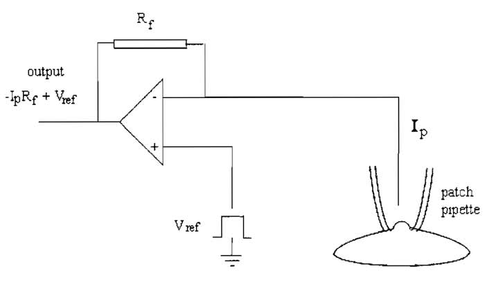 |
| FIGURE 1 A headstage current/voltage amplifier. |
IV. PATCH.CLAMP CONFIGURATIONS
The principle of the technique is to electrically isolate a patch of membrane from the external solution and record current flowing into the patch. This is achieved by pressing the tip of a heat-polished pipette onto a clean membrane. The resulting seal between pipette tip and membrane is very tight, with a resistance greater than 10GΩ, hence the term "giga seal." This is obtained using the following procedure.
- After lowering the pipette into the solution in the recording chamber, zero the voltage output to subtract the junction potential (see later).
- Apply a regular rectangular test voltage pulse of 1-10 mV for 5 ms every 20 ms to the pipette to measure its resistance. This should result in the appearance of a rectangular waveform on the current trace, which can be monitored on the oscilloscope. The pipette resistance can be worked out from Ohm's law by dividing the test voltage by the resulting current amplitude.
- Position the pipette so that it is just above the cell. Apply positive pressure to prevent the pipette tip from becoming clogged with dirt and gently blowing away any debris near the cell. This procedure will also indicate when the pipette tip is very near the cell, as the positive pressure will cause a small dimple to appear on the cell surface.
- When a small dimple is seen, a small decrease in the size of the test voltage current pulse should occur, indicating an increase in pipette resistance following contact between membrane and pipette. At this point, stop moving the pipette, release the positive pressure, and apply gentle suction, e.g., with a 1-ml syringe or by mouth. Progress of seal formation is indicated by the rectangular waveform on the current trace becoming smaller. Application of negative voltage (-50 to -60 mV) in the pipette at this stage encourages seal formation. When the pipette resistance is greater than 1 GΩ, a giga seal has been formed.
After giga-seal formation, it is now possible to record either currents from the entire cell using the whole-cell recording mode or single channel activity with cellattached, inside-out or outside-out modes (Fig. 2).
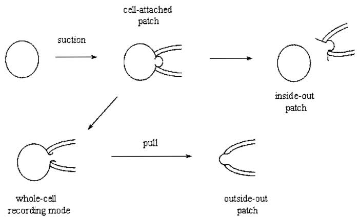 |
| FIGURE 2 Giga-seal recording configurations. |
A. Cell-Attached Recording
This configuration is not only the simplest to achieve, as it is formed by obtaining a giga seal, but it is also the most physiological. The major disadvantage of this configuration is that the resting potential of the cell is unknown, which is added to the applied pipette potential.
B. Inside-out Recording
Upon formation of a giga seal, withdrawing the pipette from the cell usually results in an excised membrane patch with its cytoplasmic side exposed to the bath solution. Inside-out patches can be used to study the influence of cytoplasmic constituents or second messengers on channel activity. A disadvantage of this configuration is that cytoplasmic constituents are lost, which may be important in modulating the behavior of ion channel proteins.
C. Whole-Cell Recording
Instead of withdrawing the patch pipette from the membrane after seal formation, application of gentle suction will disrupt the membrane patch directly under the pipette, leading to the formation of a low resistance pathway between the cell interior and the solution in the pipette. Because the cell interior is being perfused with pipette solution, this configuration has the disadvantage that certain cytosolic factors important for cellular function may be washed out. Formation of the whole-cell configuration becomes immediately apparent by the sudden appearance of large capacity transients at the leading and trailing ends of the test pulse, which reflect the charging and discharging of the capacitance of the cell membrane. These transients can be minimized using the wholecell capacitance cancellation and series resistance (Section IXA) compensation dials on the patch-clamp amplifier. This allows a crude estimation of the cell capacitance (and hence cell size) to be made because cell membranes have a fairly constant specific capacitance of 1 µF/cm2.
D. Outside-out Recording
Upon obtaining the whole-cell configuration, slow withdrawal of the pipette from the cell causes the membrane to stretch until it finally breaks. The membrane should reseal to form a patch with its intracellular face in contact with the pipette solution. This configuration can be used to study the effects of extracellular agents on single-channel activity.
E. Perforated Patch Recording
It is possible to prevent important cytosolic components from being washed out of the cell interior, whilst also allowing the electrical contact between cell interior and pipette to be sustained. Two polyene antibiotics are available, nystatin and amphotericin B, which, when present in the pipette solution, generate ionic channels within the cell membrane (Korn et al., 1991; Rae et al., 1991). These channels are small enough to permit the passage of monovalent cations and anions across the membrane, but will impede the passage of larger molecules (MW > 300). Thus, it is possible to control the concentrations of internal Na+ K+ and Cl- (in contrast, gramicidin allows only positively charged ions to cross the cell membrane, hence avoiding disruption of the membrane chloride gradient) whilst ensuring that cytosolic constituents will remain trapped within the cell. It is important that the very tip of the pipette contains only nystatin-free solution because the antibiotic impedes the formation of giga seals. To fill the pipette, the tip must first be dipped into nystatin-free solution for a few seconds and then filled with nystatin-containing solution in the usual way. Once a giga seal has formed between pipette and cell, the development of ionic channels in the membrane can be monitored by applying a -10 mV hyperpolarising pulse. As more and more channels are formed, capacity transients at the leading and trailing ends of the pulse should get larger and faster, as the series resistance of the membrane patch decreases. This process can take between 5 and 30 min. The path that is eventually formed between pipette and cell interior should be of low enough resistance to permit recordings in the whole-cell configuration. Furthermore, channels formed by the antibiotics are virtually voltage independent, enabling studies on voltagedependent channels to be performed.
F. Planar Electrode Array and Automated Patch-Clamp Recording
In addition to the conventional patch-clamp techniques described earlier, advancements have been made towards amplification and automation of this time-consuming process (Sigworth and Klemic, 2002). At present, these techniques can only be performed on cultured or dissociated cells and in the whole-cell configuration. One method employs a planar chip made from quartz in which a submicron aperture has been made (Fertig et al., 2002). The cell suspension solution is poured onto the chip and suction is applied to the apertures to secure a single cell to the aperture. Although giga-ohm resistance seals are hard to obtain with this material, advances have been made using hydrophilic-oxidised Sylgard [polydimethylsiloxane (PDMS)] instead of quartz. Advantages of the planar electrode include high-resolution, low-noise recordings due to the small diameter of the aperture; with the development of several apertures on the same chip, multiple parallel experiments can be performed simultaneously. Other automated methods, such as the PatchXpress 7000A (Axon), employ conventional glass micropipettes but use a new protocol that involves filling a glass pipette with the cell suspension solution and flushing it towards the pipette tip to create a seal with a cell (Lepple-Wienhues et al., 2003).
V. RECORDING SOLUTIONS FOR PATCH CLAMPING
The composition of solutions used to fill the pipette or bathe the cells will depend on the nature of the ion channels being investigated. A standard extracellular solution might have the following composition (mM): KCl 5, NaCl 140, CaCl2 1, MgCl2 1, and HEPES 10; while the pipette solution may be KCl 140, HEPES 10, and EGTA 10, with pH adjusted to 7.3 with NaOH in both cases. EGTA is used to buffer the intracellular calcium concentration to very low levels. Specific EGTA/Ca2+ mixtures can be used to buffer intracellular calcium at a particular value, e.g., 100 nM, and ATP, Mg2+, kinases, or other intracellular enzymes may also be added.
VI. ELECTRICAL CONTINUITY BETWEEN MEMBRANE PATCH AND RECORDING CIRCUITRY
A problem that can arise at the interface between the metal recording electrode and the pipette solution is the development of a junction potential. This potential difference arises due to the diffusional flux of anions and cations between mediums of different ionic composition or concentration. In order to overcome this problem, connections made to the recording circuitry are via nonpolarisable reversible Ag/AgCl electrodes. These electrodes consist of a silver wire with a chlorided tip produced by dipping in bleach (20% sodium hypochlorite solution) for about l min to make a nonpolarisable electrode. The electrode will turn grey/black with the formation of AgCl on the surface. The AgCl coating is fairly robust, but needs to be renewed every few days. It is also good practice to heat polish the back end of the patch pipettes in the flame of a spirit burner (Merck) before pulling so that sliding the pipette onto the silver wire electrode prevents the AgCl from being scratched off. A second AgCl wire, the reference electrode, is present in the recording chamber, which is connected to the headstage ground socket. For either of these electrodes, a good indication of the AgCl coating beginning to deteriorate can be seen from the current trace on the oscilloscope, which may display erratic 50-Hz interference or develop a considerable offset potential (50-100 mV).
VII. PATCH PIPETTES
Many of the electrophysiological properties of patch pipettes depend on the type of glass and the size and shape of the pipette tip. Pipette glass (Harvard) has an outer diameter of 1.5-2mm and is available with an internal filament running the whole length of the tube to ease filling of the pipette. The glass of choice for single-channel recording is thick-walled glass, such as borosilicate glass, as pipette capacitance and hence background noise levels are low. Noise can be reduced further by using quartz electrodes for single-channel recordings, although this incurs additional costs for materials and a specialized puller (Levis and Rae, 1998). Thin-walled borosilicate glasses are preferable for whole-cell recordings, as these provide a lower access resistance. The access resistance can also be minimized by producing pipettes with a steep angle of taper and a tip diameter of 1 µm after fire polishing to yield a low-resistance pipette (<5MΩ). In general, for small cells, relatively high pipette resistances are necessary to prevent the patched cell from being sucked up the pipette during formation of the giga seal. Lowresistance, wide-bore pipettes tend to cover a greater surface area of membrane and hence a high number of channels, and so for this reason higher pipette resistances are preferable for single-channel recordings.
A. Making Patch Pipettes
There are three stages involved in making patch pipettes: pulling the pipette, coating it with Sylgard, and fire polishing the pipette tip.
Several types of pipette pullers are available commercially (Sutter, Narishige) that pull the glass either horizontally or vertically, by mechanical or gravitational force, respectively. The pipettes are pulled over two stages: during the first, the centre of the tubing is heated in a coil of nichrome wire until it stretches over a length of around 10mm to form an hour-glass shape; at its thinnest part, the pipette should measure approximately 400-500µm in diameter. The length of the first pull determines the taper of the pipette, with a higher heat causing a steeper taper, thus reducing electrode resistance and capacitance. Once the glass has cooled, the coil is recentred around the thinnest part of the tube, heated at a lower temperature, and the two ends pulled apart to form two similar pipettes. The temperature of the second pull determines the final tip diameter, with high temperatures producing pipettes with narrow tips.
B. Coating Pipettes with Sylgard
Coating the pipette shank with an inert, hydrophobic material such as Sylgard (Merck) resin or beeswax (Sigma-Aldrich, Merck) is necessary for two reasons: (1), the pipette wall is an insulator separating two electrolyte solutions, which means that it acts as a capacitor and is thus a source of noise. This may be of particular significance for single-channel recording, where currents as small as a fraction of a pA are being measured. Because capacitance is proportional to 1/thickness, the capacitance can be reduced by coating the pipette with a thick, nonconducting layer. The hydrophobic nature of either Sylgard or beeswax also prevents the bath solution from creeping up the sides of the pipette. This will decrease the area of electrical contact between pipette and bath solution and also therefore the pipette capacitance. Sylgard is available as a resin and a curing agent, which must be mixed together in a 10:1 ratio. A good idea is to mix 10 ml of resin with 1 ml of curing agent and dispense the resulting mixture into 1 ml Eppendorf tubes. The aliquots can then be stored in the freezer until required, where the mixture remains in a fluid state. Because polymerization is temperature dependent, an aliquot will remain fluid for several hours at room temperature. Sylgard should be applied as near the pipette tip as possible without causing it to become blocked, i.e., ~100µm, and extend along the pipette to just beyond the shoulder of the pipette. It is cured by placing the pipette tip in a heated wire coil for a few seconds.
Note: Sylgard residue on the pipette tip is a potential source of consistent failure to obtain giga-ohm seals. If this happens, it is worth trying to seal with a few pipettes that have not been coated.
Beeswax is almost as effective as Sylgard in reducing noise associated with pipette capacitance, but has the advantage that its application is simpler in that wax only requires gentle heating in order to melt and dries almost instantaneously at room temperature when applied to the pipette tip.
C. Fire Polishing
Fire polishing produces a clean and smooth pipette tip with which tight seals can be obtained. In general it is best to make patch pipettes on the day that they will be used. The basic fire-polishing apparatus consists of a micromanipulator to which the pipette is attached, which is brought into close proximity to a heated platinum wire. The wire is mounted onto the stage of a microscope and is bent into a V shape in order to focus the heat onto the pipette tip. A small blob of glass is positioned onto the tip by melting the end of a pipette onto the wire. The glass blob prevents tiny fragments of the heated platinum from spluttering onto the pipette tip and making it dirty. To polish the pipette tip, the wire is heated until it glows a dull red, and the pipette is advanced towards the wire until the tip is seen to darken slightly and shrink back (by ~2µm).
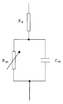 |
| FIGURE 3 A simple electrical analog of the cell. |
VIII. PITFALLS
A. Series Resistance
Because the membrane possesses channels that have finite resistance, the cell membrane can be modeled by a circuit comprising a variable resistor, Rm, in series with a parallel plate capacitor, Cm (Fig. 3). The series resistance (Rs) is introduced into the model to represent the pipette and access resistance, which is in series with the cell and the pipette during whole-cell recordings of currents. The rate at which the membrane potential is changed is restricted by the charging of the membrane capacitance. This capacity current decays exponentially with a time constant (τ) equivalent to the product of the capacitance and resistance R, where
| τ = RC | (4) |
where R = RmRs/(Rm + Rs). This means that the cell capacitance can limit the speed of the voltage clamp and the ability to observe rapidly activating ionic currents. It is also clear that the membrane resistance and series resistance influence the speed of the membrane charging. Keeping Rs low by using large-tipped pipettes with low resistance is essential for rapid clamping of the membrane voltage. Minimising Rs is also important for reducing errors in the measurement of membrane voltage and current. Several resistances contribute to Rs, with the major one being the access resistance of the pipette, usually in the order of a few MΩ. When a current flows across the membrane, the presence of Rs leads to a discrepancy between the clamped pipette potential V and the true value of the cell membrane potential, Vm. The size of the error is I×Rs and is therefore large if the current being recorded is large. It is possible to compensate for Rs electronically by adding to the command voltage a voltage signal proportional to the membrane current. In commercial amplifiers this is achieved by multiplying the series resistance value from the whole-cell transient cancellation by Ip and adding a proportion, between 80 and 90%, to Vref. Overcompensation of Rs causes the clamp circuit to oscillate. Usually Rs can change over a short time scale during recording, causing Rs measurements to be imprecise. The most accurate compensation is obtained when the initial value of Rs is low and compensation is adjusted periodically during experiments. A reasonable value of Rs would be around 10MΩ, which can often occur with pipette resistances of 4-5 MΩ. Occasionally Rs can be 50 MΩor greater.
When using whole-cell recording, it is important to quantify the errors that may arise from parameters such as Rs and cell capacitance. These values may be estimated from the current transient that arises from small voltage steps (5 mV) in the voltage range where voltage-dependent currents are inactive. Provided that Rs « Rm, the area under the capacitive transient, which gives the charge on the cell membrane (Q), can be used to calculate cell capacitance, as C = Q/V. The time constant τ is obtained by measuring the single exponential rate of decay of the capacity transient, and thus from Eq. (4) provides a value for Rs.
B. Vibration
Sources of vibration can only successfully be dampened out by the use of a vibration isolation system. Electrical recordings from Xenopus oocytes, which measure up to 1 mm in diameter, can withstand mild mechanical disturbance and therefore it may be adequate to place the microscope, manipulators, and headstage on a heavy metal base plate positioned on an air-filled rubber support, such as bicycle tyre inner tubes or tennis balls. Cell-attached and whole-cell recordings may not withstand even the mildest wobbling of the pipette tip and so a more substantial vibration isolation system is required, such as a commercial air-damped flotation table (e.g., Newport, Melles Griot).
C. Removing Unwanted Signals
In order to minimise electrical interference, principally 50Hz signals, the experimental setup must be enclosed in an earthed Faraday cage. Within the cage, all metal components, including the manipulators, flotation tabletop, and microscope, must have good, low-resistance (<1MΩ) connections to ground via a common earth point. This could be earth on the front of the oscilloscope, but most patch-clamp amplifiers also have a high-quality signal ground. The resistance between any two metal components on the setup should be measured using a multimeter and should be less than 1 Ω. All of the other instrumentation, including the oscilloscope, patch-clamp amplifier, microscope power source, computer interface, and filter, must be kept outside the cage, and it is also good practice to have shielded cables from these instruments to the main power supply as an added precaution.
IX. PATCH.CLAMP STUDIES IN CELL BIOLOGY
Perhaps the most common utilization of the patchclamp technique is the measurement of ionic currents. These can be elicited in response to changes in membrane voltage, as well as to the application of synthetic or endogenous agonists such as neurotransmitters, growth factors, and hormones. Because the cell under analysis will contain a heterogeneous population of ionic channels, it is common practice to isolate the current of interest whilst blocking the remaining components of current. Voltage protocols can be developed such that the current of interest will be activated at a particular potential where the other ionic channels will be rendered inactive (Ogden and Stanfield, 1994). It is also possible to separate ionic currents pharmacologically.
Using the patch-clamp technique it is also possible to determine if agents stimulate membrane currents directly or via intracellular second messengers. For example, the atrial muscarinic K+ channel is shown to be regulated by the βγ subunit of GTP-binding proteins using inside-out patches (Logothetis et al., 1987), whereas activation of ligand-gated ion channel receptors, including NMDA receptors, P2× receptors, GABA-A receptors, 5-HT3 receptors, and nicotinic acetylcholine receptors, is directly related to agonist binding.
The patch-clamp technique can also be exploited to measure the secretion of vesicles from the cell, quantified by measuring stepwise changes in cell membrane capacitance, which occur upon fusion of the vesicles with the cell membrane (Neher and Marty, 1982). With newer sophisticated methods of noise reduction (Johnson et al., 2002), cell capacitance measurements are now approaching resolution of the release of large synaptic vesicles into the synaptic cleft (Debus and Lindau, 2000).
Flash photolysis, which can be carried out in association with patch clamping, is a technique whereby a substance can be released rapidly inside or outside the cell from a photolabile "caged" compound present in the pipette or extracellular solution. An excellent review on the theory of flash photolysis is available (Park et al., 2002). Flash photolysis of caged calcium has demonstrated the calcium dependence of vesicle exocytosis in excitable cells (Heidelberger et al., 1994), allowing vesicle release kinetics and probability to be determined (Wolfel and Schneggenburger, 2003). Caged IP3 has been used to map out calcium release sites within nonexcitable exocrine acinar cells (Hassoni and Gray, 1994), and caged ATP has been used to modulate the activity of ATP-sensitive K+ currents (Clapp et al., 1994), as well as to determine the contribution these currents make to the resting membrane potential in pulmonary arterial myocytes (Clapp and Gurney, 1992).
References
Clapp, L. H., and Gurney, A. M. (1992). ATP-sensitive K+ channels resting potential of pulmonary arterial smooth muscle cells. Am. J. Physiol. 262, H916-H950.
Clapp, L. H., Gurney, A. M., Standen, N. B., and Langton, P. D. (1994). Properties of the ATP-sensitive K+ current activated by levcromakalim in isolated pulmonary arterial myocytes. J. Membr. Biol. 140, 205-213.
Debus, K., and Lindau, M. (2000). Resolution of patch capacitance recordings and of fusion pore conductances in small vesicles. Biophys J. 78, 2983-2997.
Fertig, N., Blick, R. H., and Behrends, J. C. (2002). Whole cell patch clamp recording performed on a planar glass chip. Biophys J. 82, 3056-3062.
Gurney, A. M. (1990). In "Receptor-Effector Coupling: A Practical Approach" (E. C. Hulme, ed.), p. 117. IRL Press. Gurney, A. M. (1994). In "Microelectrode Techniques: The Plymouth Workshop Handbook" (D. Ogden, ed.), p. 389. Company of Biologists Ltd., Cambridge, UK.
Hassoni, A., and Gray, P. T. A. (1994). Flash photolysis studies of the localization of calcium release sites in rat parotid isolated acinar cells. J. Physiol. 478, 461-467.
Heidelberger, R., Heinemann, C., Neher, E., and Matthews, G. (1994). Calcium dependence of the rate of exocytosis in a synaptic terminal. Nature 371, 513-515.
Johnson, S. L., Thomas, M. V., and Kros, C. J. (2002). Membrane capacitance measurement using patch clamp with integrated self-balancing lock-in amplifier. Pflug. Arch. 443, 653-663.
Korn, S. J., Marty, A., Connor, J. A., and Horn, R. (1991). Perforated patch recording. Methods Neurosci. 4, 264-273.
Lepple-Wienhues, A., Ferlinz, K., Seeger, A., and Schafer, A. (2003). Flip the tip: An automated, high quality, cost-effective patch clamp screen. Recept. Channels 9, 13-17.
Levis, R. A., and Rae, J. L. (1998). Low-noise patch-clamp techniques. Methods Enzymol. 293, 218-266.
Logothetis, D. E., Kurachi, Y., Galper, J., Neer, E. J., and Clapham, D. E. (1987). The βγ subunits of GTP-binding proteins activate the muscarinic K+ channel in heart. Nature 325, 321-326.
Neher, E., and Marty, A. (1982). Discrete changes of cell membrane capacitance observed under conditions of enhanced secretion in bovine adrenal chromaffin cells. Proc. Natl. Acad. Sci. USA 79, 6712-6716.
Neher, E., and Sakmann, B. (1976). Single channel currents recorded from membrane of denervated frog muscle fibres. Nature 260, 799-802.
Ogden, D., and Stanfield, P. (1994). In "Microelectrode Techniques: The Plymouth Workshop Handbook" (D. Ogden, ed.), p. 53. Company of Biologists Ltd., Cambridge, UK.
Park, M. K., Tepikin, A. V., and Petersen, O. H. (2002). What can we learn about cell signalling by combining optical imaging and patch clamp techniques? Pflug. Arch. 444, 305-316.
Rae, J., Cooper, K., Gates, G., and Watsky, M. (1991). Low access resistance perforated patch recordings using amphotericin B. J. Neurosci. Methods 37, 15-26.
Sakmann, B., and Neher, E. (eds.) (1995). "Single-Channel Recordings" Plenum, New York.
Sigworth, E J., and Klemic, K. G. (2002). Patch clamp on a chip. Biophys J. 82, 2831-2832.
Voipio, J., Pasternack, M., and MacLeod, K. (1994). In "Microelectrode Techniques: The Plymouth Workshop Handbook" (D. Ogden, ed.), p. 275. Company of Biologists Ltd., Cambridge, UK.
Wolfel, M., and Schneggenburger, R. (2003). Presynaptic capacitance measurements and Ca2+ uncaging reveal submillisecond exocytosis kinetics and characterize the Ca2+ sensitivity of vesicle pool depletion at a fast CNS synapse. J. Neurosci. 23, 7059-7068.
Support our developers


